PCI-E question

looking at it that would have required some work to swap the ground and 5 volt contacts.
Just connect the red wire from the fan to the yellow 12v terminal and the black wire from the fan to the red 5 v terminal within the psu itself. Would be nice if you can solder it right on those terminals. 12 - 5 = 7 volts to the fan, which is close to where your at with that voltage reg. Read the printed voltages on the molex terminals on that link I provided in my last post to see what I mean.
Edit* molex connector not required, do not need to use one
 
Last edited:
The fan came with both a three pin and four pin connector. The four pin molex is the type that has both a plug and jack on it so that it could be inserted between a device and the four pin molex power connector.

I would have simply swapped the +5 and ground contact in that connector.

I can see about soldering to the power supply board which would eliminate two wires.

The power supply does have a two pin fan connector that will fit a three pin fan plug, but when I tried the 12 volt high speed fan on that connector the fan just would run and I think the voltage on that connector was lower maybe the stock power supply fan was 5 volts or a 12 volt fan designed to run at some speed on such a low voltage.

I didn't think about soldering to the power supply board, however I would rather have soldered a three pin fan connector to it so that when this fan fails I can easily replace it. Only issue is I already had cut the three pin fan connector off the cable, however I'm pretty sure that I have another three pin connector I can use.

I might try the built in fan controller of the power supply and see if the fan can run on it. If not I may see if its possible to increase the voltage to the fan connector or I may cut the traces to the fan connector and wire it to 12 and 5 volts so that the fan gets 7 volts.

Would be nice if there was a way I could swap in the center piece of a fan with bearings and the motor while keeping the rest of the fan stock.

The fan didn't cost much so I may buy another and look into doing that if there's not much work involved, however one wire of each LED if not both goes to the fan motor directly so I'd have to look at that and figure how the LEDs are being powered then figure how to power them.

One things for sure this fan doesn't seem to spin quite as freely as a fan with bearings does and if I hold the fan to where it's blowing down it tends to slow down slightly.

I've thought about taking the rear of the supply where the air inlet is and making a hole there about the size of a 3" fan. I'd either put a grill over it or I'd put another of the same 3" fans on the outside blowing air in. I could then wire the fans in series on the 12 volt line.

I need to look at all the wiring and see how I can neaten it up.
 
Took the power supply to work today where I have better soldering and test equipment.

Spent about three hours poking and prodding around the daughter card that the fan connects to.

Tried various things and learned through trial and error that if everything on that board isn't exactly right the power supply shuts down immediately and once AC power is removed you have to wait until the +5V standby drains down before the supply works again.

The fan voltage starts out at 3.6Vdc and as the heatsink heats up it will reach 11.95Vdc.

I found a resistor that is used on the output of the fan to feed the voltage back to a chip. It's 1 meg. I tried a 1 meg in series and that brought the fan voltage up to 6.8Vdc. The fan is thusfore still temp controlled, although I seriously doubt this PC will ever draw enough power to make the fan speed up. I tested it by blowing a small heat gun on the heatsink and as expected the fan did increase speed as the temperature of the heatsink increased.
 
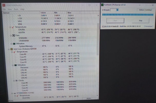
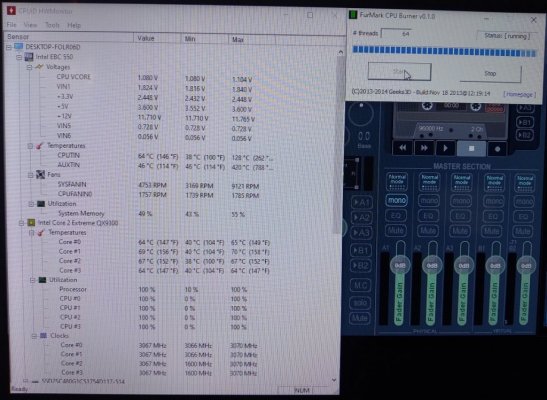
To show how much the liquid cooling helped me out I used both PCs which are set up the exact same except one uses the blower and heatsink an the other uses the liquid cooling.

Computer with heatsink and fan after about 30 seconds running the program.

22.jpg

Computer with liquid cooling which had been running the program about 3 minutes. The coolant temp only rose by 1 degree.

11.jpg

I also ordered these.

https://www.amazon.com/dp/B08RYPRZFF?psc=1&ref=ppx_yo2_dt_b_product_details

I'll use the red one for +5V the yellow one for +12V the blue or green one for +3.3V since they did not have an orange one and I might use whichever color I don't use for the +3.3V for the power supply fan voltage.

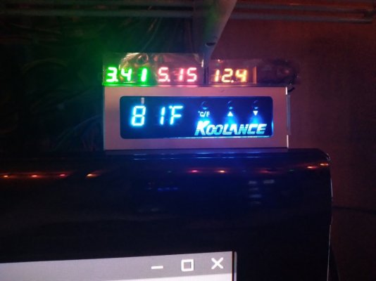
Why, because it's an easy way to monitor the voltages and it looks cool to me.

I'm sire I'll have to adjust the cal pot but I'll put my DMM in parallel with each one and adjust until the display matches what my DMM reads since I know it's accurate.

EDIT:

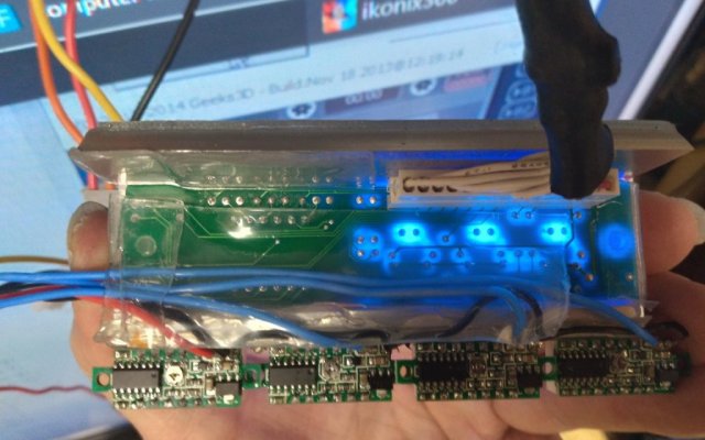
The modules were smaller than I thought. Only had to slightly tweak one cal pot.

Mounted them to the top of the temp display for the liquid cooling.

33.jpg

The green display is quite bright and I suspect the blue will be too so I'll need something to put in front of the displays to make them look dimmer.

The blue isn't connected yet (suspect will be just as bright) as it is for the power supply fan voltage (changes with temperature) and I want it on a connector in case I have to disconnect the power supply so I'm gonna use this as it will allow the internal fan to connect and the other jack can be routed out the rear of the supply for the plug for the voltage display.

https://www.amazon.com/Splitter-Extension-Sleeving-Connectors-Length/dp/B00C46DX4S/ref=sr_1_11?crid=1E1I5L9ETITX1&keywords=3+pin+fan+splitter&qid=1645047137&sprefix=3+pin+fan+splitter,aps,192&sr=8-11

44.jpg

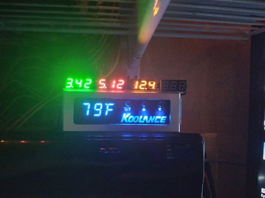
I used red and yellow for the voltages they show as I wanted to match the wiring color code. Would have been nice if they had an orange module.

That said do the supply voltages look ok?

The Gorilla brand of double sided tape is some amazing stuff. Has the best hold out of any of the double sided tapes I've used and once removed it isn't very difficult to completely remove the left over pieces from whatever it was on and it leaves no real residue.

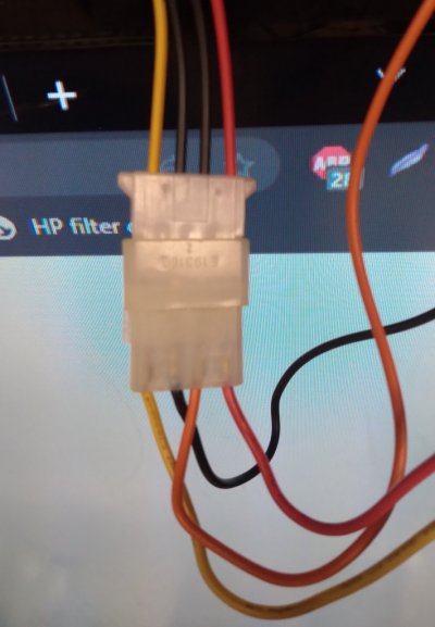
To connect it up I found a four pin connector that just so happened to have +3.3 +5 +12 and ground so I wired it up to a four pin molex jack that came from a molex to SATA adapter cable so that it could not be inadvertently plugged into anything by mistake if I should disconnect then reconnect the power supply. I then put a molex plug on the voltmeter end.

55.jpg
 
Last edited:
Just did an extended test of about 10 minutes running the cpu burner program without the radiator fans connected and the CPU temp slowly climbed to 123F while the coolant temperature slowly climbed to 99F.

Turned the program off and re-connected the fans. Processor temp is at 104F and the coolant temp after about a minute is 93F.

Now after about three minutes processor temp is 95F coolant temp is 84F.

EDIT:

Happened to see the ESD packaging the modules came in. Looked at it and it is see through. I thought perfect thing to dim the displays with. The camera makes it look worse than it is.

66.jpg
 
Last edited:
Only thing I sort of forgot about is that I believe the motherboard has its own regulators for the 3.3 volts as even though the stock power supply had a 3.3 volt line the motherboard power supply plug pinout showed nothing there.

So technically I really didn't need the meter for the 3.3 volt line, however the SATA power plugs do have a 3.3 volt wire going to them and some SATA stuff does use 3.3 volts (not sure if my SSD drive does or not) so maybe it was good I included the voltmeter for it.

I do know there's a brown wire that was on the main motherboard power supply plug before I swapped it with the one for this motherboard.

Looking online it says the brown wire is for the 3.3 volt sense.

The supply works ok as is.

Do I need to connect the brown wire to the 3.3 volt wire?

The copyright date on the label on the side of the supply is 2007 and I'm thinking I built it in 2004 and got the supply three years later.

So does the brown wire being 3.3 volt sense apply?
 
I measured 3.33Vdc on the brown wire.

What I'm wondering is if the supply has a built in resistor to make that line have some voltage on it so for motherboards that don't use the sense wire or the 3.3 volt line the power supply will still function normally. Some motherboards used on board regulators for the processor voltage.

Power supply is an Antec Earthwatts EA-500D.

So far with just replacing the electrolytic capacitors the supply is working great.

Honestly I'm surprised the supply even worked at all with those bulged caps.

Most of the time when caps bulge like that in a switch mode power supply it will sit there and cycle off and on which I suppose is the current limit of the supply being reached due to the cap being shorted.

Also according to the ATX specification

https://cdn.instructables.com/ORIG/FS8/5ILB/GU59Z1AT/FS85ILBGU59Z1AT.pdf

my voltages are within spec, although the +12 volt line at 12.44Vdc is almost out of spec with the spec being 12.6-11.4Vdc. Does the spec assume slight voltage drop of the wiring based on the current draw?

Now when I get the money I'll build a gaming PC then this PC will be for my streaming while the other identical PC will be relegated to more of a server role. To do that so I do not have to re-install stuff I may swap hard drives. I'd then install one or two high capacity drives rated for Network Attached Storage use.

One for folders that I want access to from any PC.
One for complete images of all hard drives of all PCs.

That way should a PC hard drive go down or otherwise get compromised I would lose at most maybe a days worth of info if I back up every day. I would connect my hard drive dock to that PC so that if I needed to replace a drive I can simply drop the drive in the dock and copy the drive image to it.

EDIT:

Looks like mine is an ATX 2.0 spec supply but may have been compatible with ATX 1.0 as the four pin connector I used for the +3.3 +5 +12 and ground for the voltmeters would have fit on the 20 pin connector to make it the 24 pin connector of the ATX 2.0 standard.

Mine also has two PCI-E six pin connectors Three ground and three +12 volt.

Also has an 8 pin connector. Four ground four +12 volt although those 12 volt wires are yellow with black stripe, but read the same as the other +12V lines.
 
Last edited:
I decided to try connecting the brown wire to the 3.3 volt rail. I used a 510 ohm resistor just in case so that I wouldn't risk damaging anything if I was wrong about that wire.

With it connected the 3.42 volts dropped to 3.39 volts. So apparently it has an internal resistor from the brown wire to the 3.3 volt rail or some other means of monitoring the 3.3 volt rail independent of the brown wire.

I then connected the brown wire to an orange wire and the voltage dropped to 3.35 volts. If I knew something was actually using the 3.3 volt line I'd splice into the orange wire at that device.
 
So far so good.

I got the fan splitter installed so I could have the far right voltmeter indicate fan voltage. It varies from about 6.99 to 7.20 based on room temperature and what I'm doing with the computer.

Normally I prefer fans running at full speed, but since the PSU barely heats up with the fan running slow I saw no need to run the fan full speed.

The two 40mm fans (one on the motherboard graphics/PCI-E chip and another chip) I ran off the pump voltage regulator to quieten them down and one I replaced with the thicker 40mm fan I used to have on the CPU heatsink as the built in video/PCI-E chip got a bit warm when I slowed the fan down so I needed the extra airflow at a slower fan speed.

Now the PC is real quiet.

I'm tempted to do the same to the other PC.

However once I build a gaming PC the PC with liquid cooling will be the stream PC and I'll simply swap hard drives between the two identical PCs. The other PC will be more of a server so it won't need as much cooling and I could possibly revert it back to the original display so that it is more compact again.
 
Back
Top Bottom