Meta_Alchemy
Beta member
- Messages
- 1
- Location
- United States
Greetings,
This is a most wonderful site to be in. Treated me like a king before I even stepped through the door.
Here I am with my problems.")
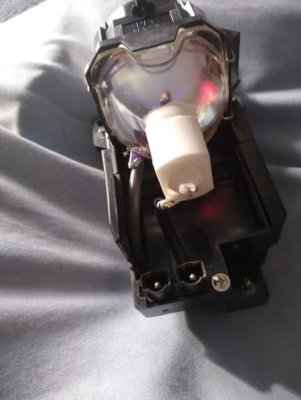
I sure like to light up this lamp that I took out of a Hitachi wall projector that had couple of things missing. So as usual I just take things apart. Basically electronic stuff. I just like to get lost in circuit boards. If knew it was this much fun I would started the minute I outgrew my diapers.
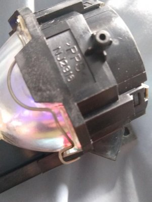
This lamp lit up nice when It was in the projector unit so I know it is good.
I paid close attention how power was supplied to it.
I have the power supply and the control board. They are two little separate boards but nothing too involved. House supply to its power supply and then a wire from that board to the control board. From the control board the only wires that go to user board is in the picture, it is where my question is.
When I hooked up the light directly to a 50-60 volt dc power supply, nothing, no response. It is the maxium dc power supply that I have.
So I need to provide power via its board.
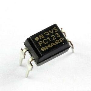
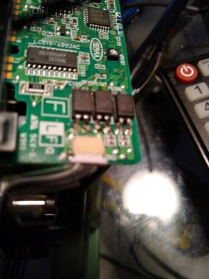
As you can see form the picture there is 3 optocoupler. 5 wires feed it.
What voltage should I apply in what manner to these 5 wires. (1 green, 4 brown wires)
One optocoupler as you know consists of 4 connections. two power in (anode and cathode) and two power out.
I am not sure how you get 5 wires feeding 3 optocouplers.
I am trying to edit to ad a closer shot of the wires that feed the optos but I don't see the option to add image. Although you can see those wires in the picture of the board, a closer shot will only show that it is one white and 4 brown wires and nothing new
My main interest is that these lamps are quite bright, it would be nice to have them around the house or in my garage or wherever to show off.
Thank you in advance.
This is a most wonderful site to be in. Treated me like a king before I even stepped through the door.
Here I am with my problems.
I sure like to light up this lamp that I took out of a Hitachi wall projector that had couple of things missing. So as usual I just take things apart. Basically electronic stuff. I just like to get lost in circuit boards. If knew it was this much fun I would started the minute I outgrew my diapers.
This lamp lit up nice when It was in the projector unit so I know it is good.
I paid close attention how power was supplied to it.
I have the power supply and the control board. They are two little separate boards but nothing too involved. House supply to its power supply and then a wire from that board to the control board. From the control board the only wires that go to user board is in the picture, it is where my question is.
When I hooked up the light directly to a 50-60 volt dc power supply, nothing, no response. It is the maxium dc power supply that I have.
So I need to provide power via its board.
As you can see form the picture there is 3 optocoupler. 5 wires feed it.
What voltage should I apply in what manner to these 5 wires. (1 green, 4 brown wires)
One optocoupler as you know consists of 4 connections. two power in (anode and cathode) and two power out.
I am not sure how you get 5 wires feeding 3 optocouplers.
I am trying to edit to ad a closer shot of the wires that feed the optos but I don't see the option to add image. Although you can see those wires in the picture of the board, a closer shot will only show that it is one white and 4 brown wires and nothing new
My main interest is that these lamps are quite bright, it would be nice to have them around the house or in my garage or wherever to show off.
Thank you in advance.
Attachments
Last edited: