This looks like what I was looking for and I have maplins round the corner from me, only thing to add to this is if its possible to flip the switch and when the blind reaches the top it stops the motor. This is why I thought i'd need a PCB board to program the motor to stop after a certain distance (time) ?
for distance. You'll need either a micro switch, (so that there is a switch pressed when the thing gets to the top/bottom, or on of those light gate things...
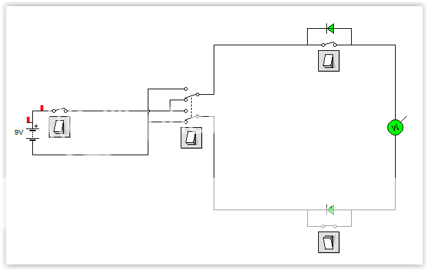
and a couple of diodes
(i'd probably go with the switch since the come with a nice big lever that can be hit anywhere along the bar to stop the bind, whilst if you go for a light sensor based one you need to make sure your flag if lined up properly to go into the slot, if a little breeze means that the flag doesn't go into the hole properly, then you can keep your blind going.)
essentially, you have the switch set inline with the circuit, so that it's normally closed state will let power run in any direction. and then you have the diode bridging the switch so that when it get's to the top. the switch contacts break apart, and the diode is also blocking the flow of current to let the motor wind up any more.
But when you press down, whilst the switch contacts are still broken and won't allow current to flow, the diode will allow current to flow, (but only letting the motor spin in the down direction). that way you wind down with current going through the diode, the micro switch resets and then current will pass through the switch letting you do either up or down once again.
I'll draw out the circuit diagram when I get home, (or sometime over the weekend) so you know what connections go where.
if you want it done as a function of time, (i,e I press a button and it winds for three seconds only, press again and it'll wind for three seconds.
then you'll need a timer. (and a relay since there is a limit to the amount of current the chip you use could either source or sink.)
this can either be done using a 555 one shot timer, (otherwise known as a monostable multivibrator) or using a microchip (Ardiuno (if you want the whole devboard) Atmel, PIC etc for just the chip.) - I'd recommend the 555 approach, not least because it is simple, but it's the most useful in terms of learning...
(t = 1/rc) to set the time - i.e you just replace a resistor or capacitor to change the time the circuit stays on for.
or you have to go back to your source code/sketch
change the bit that says :
portb = 1; //set motor on
delay_ms(3000); // wait 3 seconds
portb=0; //turn motor off
then recompile and upload the new firmware (which may involve taking the thing apart, if you're done it with an IC instead of a DEV board then you may have to unsolder the chip (unless you used a chip socket)
Whichever you choose both timer approaches will require a PCB,
Just putting the micro switches inline and diodes across them can be done without a circuit board. (but obviously it's not as cool as pressing a button and walking away.)
 I think the diode is a better option than a timer as I want a simple setup.