D4rkfalz
Beta member
- Messages
- 3
- Location
- Kent, Washington
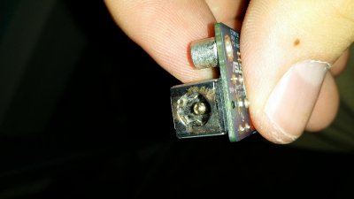
Greetings, had a couple questions regarding repairing a bad DC Board in my ASUS G75VW. A few days ago my laptop slid off of my desk onto carpet, absorbing most of the impact though this did not stop the charger jack from dinging against a wall and bending it. Now the steps forward I took were not ones that I am proud of while waiting for my new charger to come in. I had straightened most of the port out and electric taped the plastic housing and kind of gently put it in the laptop port. This was mostly out of desperation of needing to get a project out in time and greatly I regret it now.
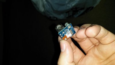
After completing my project I noticed a slight spark come from the port and immediately got the cord disconnected and awaited my new charger. My charger arrived today and I plugged it in, powering up my computer and charging my battery to 100%. Once my battery was done charging I noticed my screen flicker, followed by a no longer charging, charging then finally another no longer charging warning meanwhile my lamp also flickered. At this point I noticed that the power block of my new charger was no longer lit and i figured at that point the power surge killed it. All this happened while my laptop was on and fully functioning minus the inability to take a charge. I managed to order another charger and dismantled my laptop and will submit several images of the DC mini board.
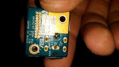
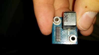
Upon examination of the actual DC port, it was fried/charred/mangled and nasty while the board it was on seemed new and untouched. I went and ordered a replacement of JUST the port for 6$ since I do not want to spend $80 for the whole mini board since I have the means to solder a new one on since I did that for roughly 3 years. What I come to you guys in help of is I wanted to now if there was a way to test the voltage of the port and charger connected together (just the miniboard/port to the charger/wall) using a multimeter to see if the board in fact fried too and will cause another surge?
I don't want to fry another charger and I am curious if there is a way to test and if so what settings and where would I place the prongs (not familiar with multimeters and testing voltages >.>) and I assume since its a 180 W 19.5V, 9.5 Amp charger I would be seeking those readings. Granted this is not possible, I wouldn't mind some more opinions on how the mini boards function and whether its possible for the board itself to be fried without showing no visible damage. I'm really just hoping its the port itself that i can replace. What do you guys think?
After completing my project I noticed a slight spark come from the port and immediately got the cord disconnected and awaited my new charger. My charger arrived today and I plugged it in, powering up my computer and charging my battery to 100%. Once my battery was done charging I noticed my screen flicker, followed by a no longer charging, charging then finally another no longer charging warning meanwhile my lamp also flickered. At this point I noticed that the power block of my new charger was no longer lit and i figured at that point the power surge killed it. All this happened while my laptop was on and fully functioning minus the inability to take a charge. I managed to order another charger and dismantled my laptop and will submit several images of the DC mini board.
Upon examination of the actual DC port, it was fried/charred/mangled and nasty while the board it was on seemed new and untouched. I went and ordered a replacement of JUST the port for 6$ since I do not want to spend $80 for the whole mini board since I have the means to solder a new one on since I did that for roughly 3 years. What I come to you guys in help of is I wanted to now if there was a way to test the voltage of the port and charger connected together (just the miniboard/port to the charger/wall) using a multimeter to see if the board in fact fried too and will cause another surge?
I don't want to fry another charger and I am curious if there is a way to test and if so what settings and where would I place the prongs (not familiar with multimeters and testing voltages >.>) and I assume since its a 180 W 19.5V, 9.5 Amp charger I would be seeking those readings. Granted this is not possible, I wouldn't mind some more opinions on how the mini boards function and whether its possible for the board itself to be fried without showing no visible damage. I'm really just hoping its the port itself that i can replace. What do you guys think?
Attachments
Last edited:
