Project: Aluminum Water Cooling Case

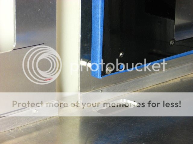
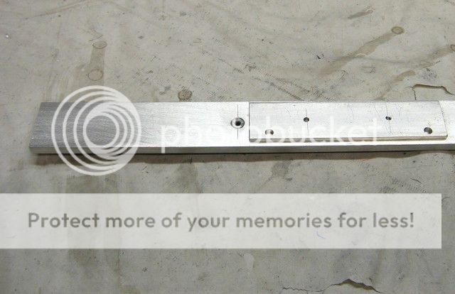
In order to accurately drill the bolt holes to attach the perforated aluminum to the side panels, I fabricated a drill template from some left over flat bar stock and a drill bushing I had lying around the shop.

DrillGuide.jpg


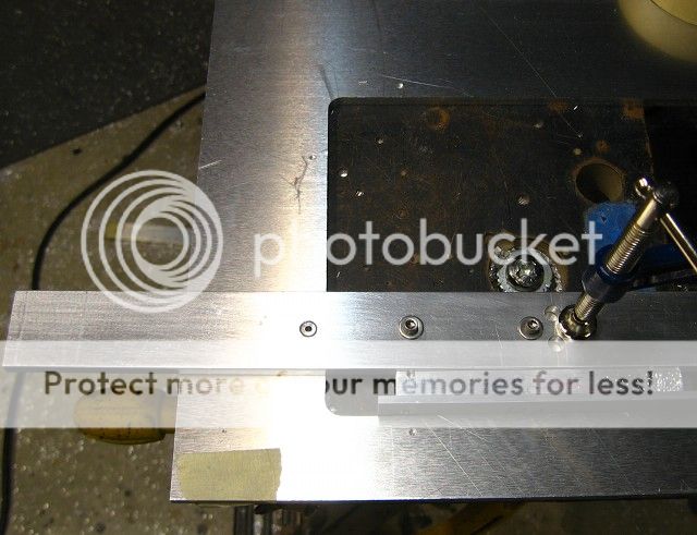
A couple of spacers was used to quickly and accurately place the jig on the work piece (to avoid having to measure/layout the location of the holes).

DrillGuideInAction.jpg


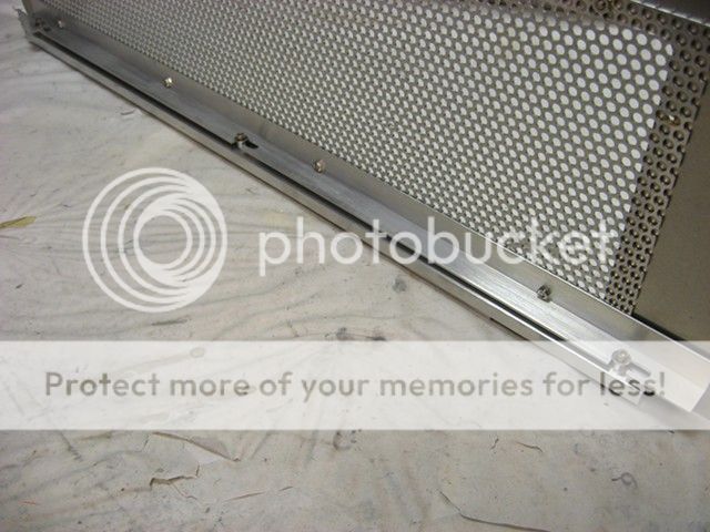
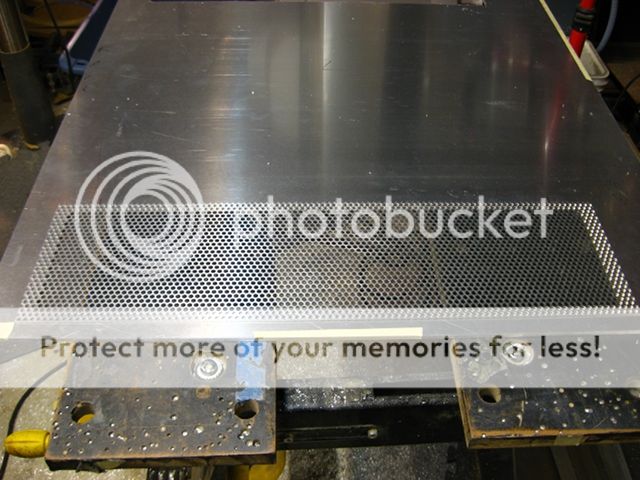
Some .063 perforated aluminum cut to size:

SidePanelPerforatedAlCut.jpg


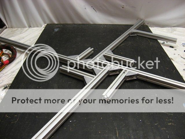
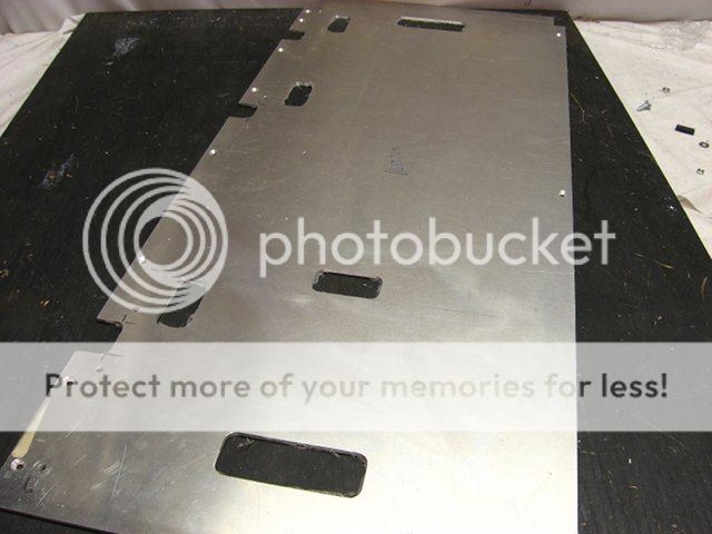
To accurately cut the rounded corners on the side panels a router jig was fab'd from a piece of the corner round used on the body of the case, 1-inch u-channel and a couple of 1-2-3 block hot glued to some particle board. Two strips of Mylar from an old drum head was used to smooth out any irregularities.
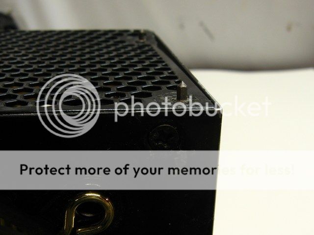
CornerRoundingJig.jpg


Tah-dah!

CornerRounded.jpg


SidePanelWithPerfAL.jpg
 
Another requirement for this case is a hidden door latching mechanism.

Look Ma! No latches!

LeftDoorLatched.jpg


A length of .125x.75-inch flat bar was bolted to the bottom of the door to act as a lip that will hook into the u-channel along the bottom of the case, for example:

BottomHookExample.jpg


Along the top of the door, there is a piece of angle with three "hooks", which were routed out using a cobbled together router template.

DoorHookTemplate.jpg


TopDoorHooks.jpg


A thick piece of flat bar was filed down to where it'll slide easily inside the u-channel along the top of the case. To that three "posts" were bolted to it. When slid forward, the posts will engage the hooks.

DoorHooksNotEngaged.jpg


DoorHooksEngaged.jpg
 
I made a mistake, placing the false back too far into the case, which required having to re-fabricate the back sheet. But I figured I could take advantage of the situation by improving the mounting of the motherboard tray, by fastening the tray to the false back with a 7/8-inch long spacer.

MBTraySpacer.jpg


I don't remember if I already offered this tip before, but I try to reduce the wear and tear on my 1/2-inch flush cutting router bit by first rough cutting with a 3/16-inch spiral downward cutting bit.

MBTrayHoleCutW316Bit.jpg
 
A PSU mounting plate was routed out of a piece .10-inch thick aluminum sheet with the help of a custom template.

In order to accurately transfer the locations of the PSU mounting holes, threaded hole transfer punches (mcmaster.com part # 3385A31) were threaded into a PSU.

ThreadedHoleTransferPunches.jpg


TransferPunchInPSU.jpg


And then the PSU was carefully centered and pressed into the sheeting, with the end result being a perfect squarely mounted PSU.

PSUMountingPlate.jpg
 
Another router template was made to cutout the areas for the PSUs out of the back sheet. A guide was clamped to the bottom of the template to keep the cutouts perfectly aligned along the bottom.

PSUPattern.jpg


PSUCutOut.jpg


PSUCutOuts.jpg


PSUCutOutWithPSU.jpg
 
Turned out that I needed to cut one more slot out of the bottom shelf. But the last time I used my wooden "small slot" router template, I somehow managed to crush one edge, so I quickly cobbled together a new out of some left over t-slot extrusion. I'm really loving using these t-slot extrusions to make router templates - fast and accurate!

RouterTemplateMadeFromExtrusions.jpg


Here's a teeth-shattering video of me cutting out the slot.


SmallSlotOutOfBottomNearFront.jpg
 
Back
Top Bottom