Project: Aluminum Water Cooling Case

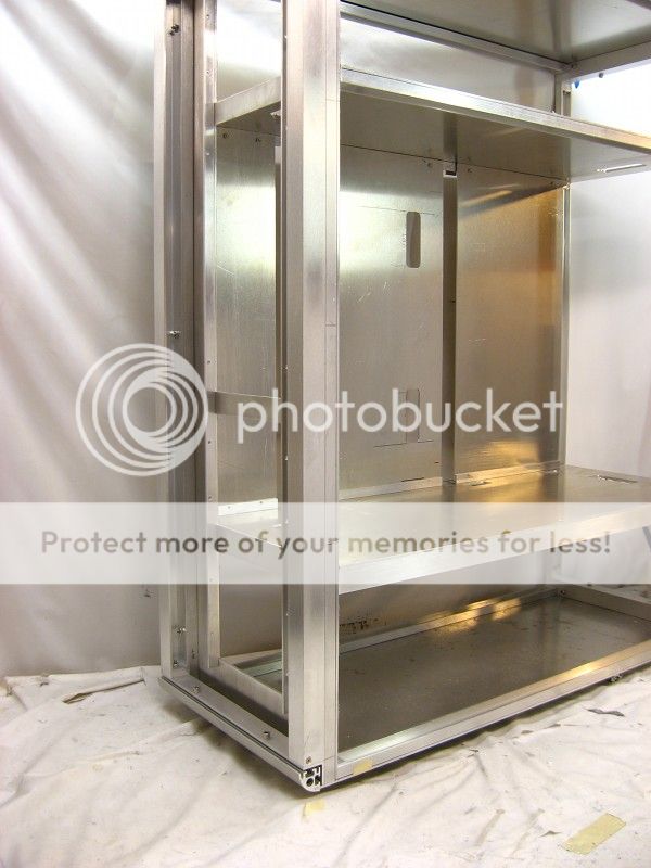
Two cutouts were routed out of the back sheet for the bottom mounted PSU (left hand side of the pic) and intake fan, and two intake fans up top.

BackSheetwCutouts.jpg


Eventually, some "adapter plates" will be mounted over the two cutouts.


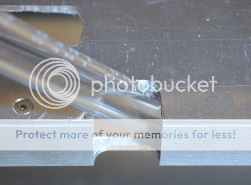
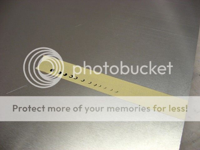
To attach the MB tray to the back sheet, four PEM cinch nuts were pressed into the interior side of the .10-inch thick aluminum sheet. I love these nuts because they make quick work out of adding some threads to sheet metal.

BackSheetPEMNuts.jpg


BackSheetPEMNutsInterior.jpg


BackSheetwCutoutsAndMB.jpg
 
Another awesome feature of this case is the "false" back, which is simply a sheet of aluminum between the removable back panel and the motherboard tray. The "false" back prevents the case from racking and is the primary cable management feature. In this case, the "false" back consists of three pieces of .10-inch thick aluminum.

The sheets that make-up the "false" back are threaded along the top via PEM nuts. Fastening them to the top support beam is simplified via the addition of slots routed out of the support beam. These allow the hex wrench to be raised into position as the socket cap screws are driven into the sheet.

FalseBackSupportHoles.jpg


FalseBackSupport.jpg


FalseBackTopBack.jpg


FalseBackBack.jpg


Along the bottom, the sheets are fastened to some 1/2-inch angle.

FalseBackBottomBack.jpg


FalseBackFront.jpg
 
Slots for wire and tube routing were cut out of the top and bottom shelves. I attempted to use a pattern router bit, but the deep cut forced the bit's bearing into the 3/8-inch thick particle board, ruining it.

RouterBitGuide.jpg


So I switched to using a pattern to guide the base of the router.

RouterBaseTemplate.jpg


The slots along the edge of the bottom shelf were cut in such a way to allow tubing and wiring to pass without significantly weakening the 1/2 x 1-inch u-channel.

TubeAndWireRoutingSlot.jpg


Bottom shelf slots:

WireRoutingSlotsInBottomShelf.jpg


Top shelf slots:

WireRoutingSlotsInTopShelf.jpg


WireRoutingSlotsInShelves.jpg


Finally, two slots were also cut out of a portion of the "false" back:

WireRoutingSlotsInFalseBack.jpg
 
Jesus, that's almost a FOOT taller than my tallest case, and appears to be 2-4 inches wider, and a WHOLE lot deeper... Dunno how that thing can ever be filled up xD
 
Up until now the front of the case has been held on with masking tape, but its now time to attach it securely. I had originally planned on drilling through holes and bolting the front to the case, but there wasn't much room for my hands to hold onto a nut, so I increased the size of the through hole a bit and pressed-in some PEM nuts.

FrontPEMNuts.jpg


The front frame consists of 1x1 and 1/2x1 u-channels.

FrontFrameAssembly.jpg


AttachingFrontFrame.jpg


Button head bolts were used to attach the front to the case.

FrontFrameAttachmentBolts.jpg
 
The side panels were cut via the help of a large makeshift square made from a small square clamped to a ruler.

MakeShiftTSquareA.jpg


MakeShiftTSquare1.jpg


The radiator ventilation cutouts were made with the help of a router template. Some bits of scrap aluminum were bolted to the underside to eliminate any errors with placing the template accurately on the sheets.

RadCutOutsTemplate.jpg


Determining where to make the cutouts was easily done via a dab of India ink on the head of a screw and some masking tape. The panel was repeatedly pushed up against the inked bolt.

IndiaInkCU.jpg


InkMarkings.jpg


LeftSidePanelCut.jpg
 
Back
Top Bottom