Project: Server and Gaming Case

Status
Not open for further replies.
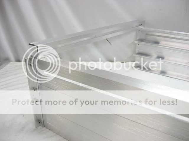
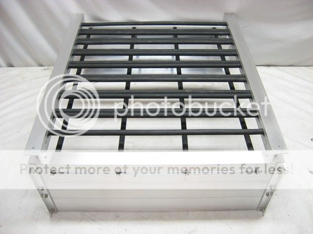
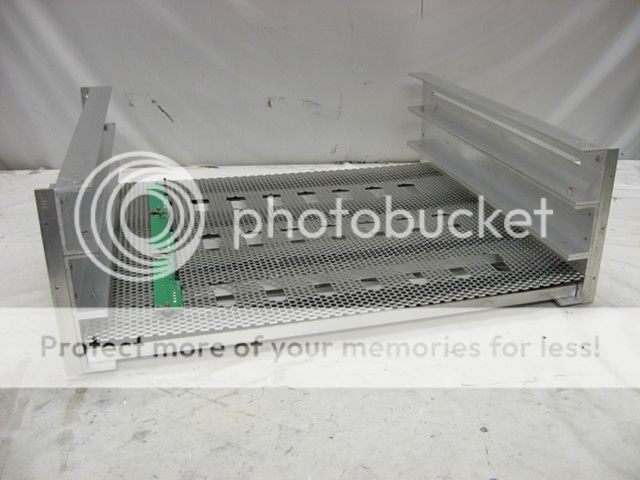
I spent the day correcting a big mistake, which was I relied on the incorrect posted dimensions of the Swiftech MCR320-DRIVE 3x120 radiator, and thus the case wasn't wide enough by 16mm. (Swiftech has since corrected the diagram on their website).

CorrectLengthOfMCR320-DRIVE3x120Radiator.jpg


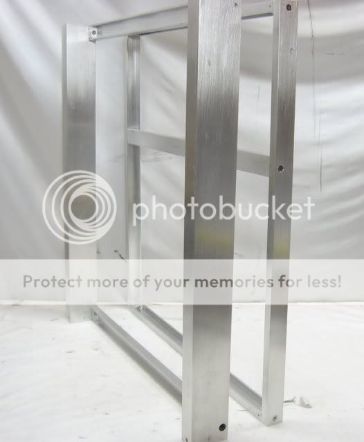
Actually, the case was exactly the width of the rads, but that might have resulted in some pump vibration getting transfered to the side panels. So the case had to be widened by one inch.


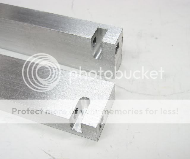
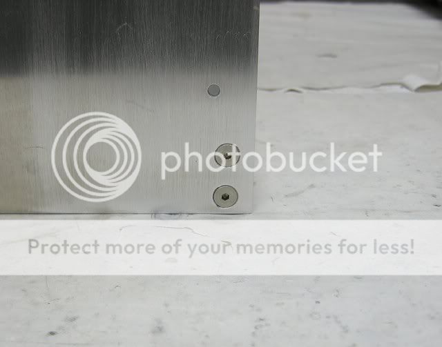
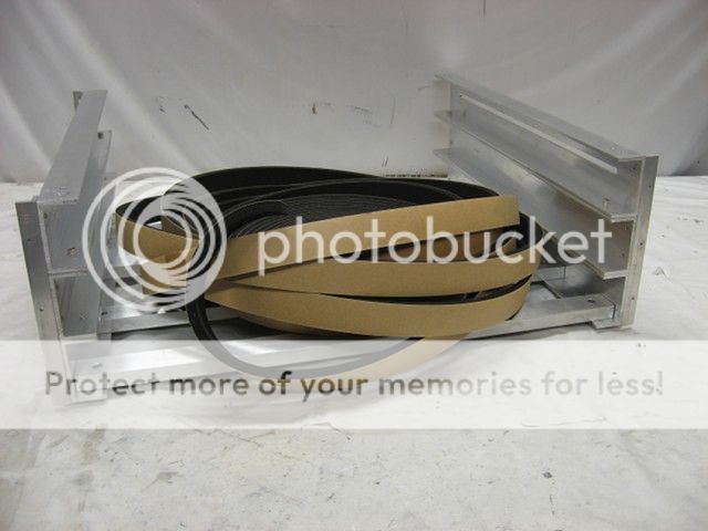
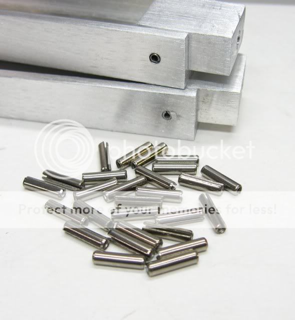
To speedup the process of pinning the bolt blocks to the u-channel I switched to using split pins.

SplitPins.jpg


BackFramePartsPinnedWSplitPins.jpg


WiderBackAndFrontFrames.jpg


WiderBackFrame.jpg


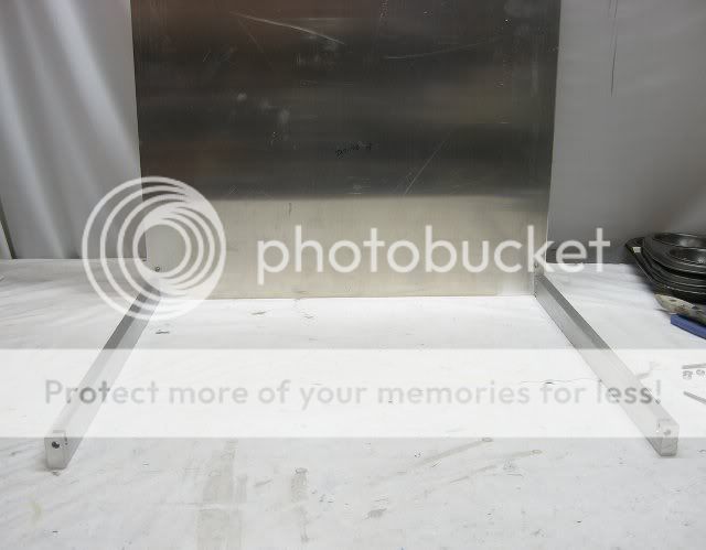
I also had to re-cut the back sheet.

WiderBackFramewBottomSheet.jpg


Altogether, it only took me about a third of the original amount of time. Phew!
 
The bottom support beams were made from .5x.1-inch aluminum flat bar. I wasn't keen on having to hand drill and tap them, so instead, I routed grooves to accept nuts.

NutSlots1.jpg


NutSlots2.jpg


I like this fastening method because its wicked strong and offers just enough "play" for easy assembly.

AssembledNutSlots.jpg


The frame is bolted to the front inner sheet.

InnerFrontSheetFHCU.jpg


And then the entire subassembly is bolted to the front frame.

BeamsToFrontSheet.jpg


FrameFromBack.jpg


FrameFromFront.jpg
 
The sides of the HD cage consists of three pieces of .125-inch thick 1x1.5-inch u-channel held together with some threaded bolts. The cage will be bolted to the frame of the case via some .5-inch angle.

HDCageSides.jpg


The holes in the angle were used to guide the drill bit into the side pieces.

HDCageSidesDrillingCU.jpg


HDCageSides2.jpg


HDCageSidesCU1.jpg


Quarter inch slots were routed out of the u-channels to eventually accept .25-inch threaded rods.

HDCageMockup1.jpg


HDCageMockup3.jpg


HDCageMockup2.jpg
 
Santoprene rubber/plastic tubing was slipped over 1/4-inch threaded rods to form a "cage" to contain the HDs.

HDCageParts.jpg


Here's why the routed slots are superior to individual holes.

HDCageAssembly.jpg


HDCage.jpg


HDCageMockup.jpg
 
A last minute design change was to go with SATA backplanes. This required having to route-out 24 phalanx shaped areas for the LED and power cables to pass through.

BackplaneTemplate.jpg


[These photos are just quick mockups, the perforate aluminum will eventually get mounted to the bottom of the drive cage. ]

Backplanesheet1.jpg


Backplanesheet2.jpg


The backplanes rest on some soft rubber grommets and are attached via two #4 socket head cap screws.

The 1/16-inch perforated aluminum was a good choice because I didn't have to drill a boat load of holes.

BackplaneMockupCU2.jpg


BackplaneMockupCU1.jpg
 
I finished the bottom of the HD cage by adding four support beams made from 1x.5-inch u-channels.

HDCageBottom.jpg


HDCageBottomCU.jpg


To further dampen vibrations some 1x.25-inch soft foam will be stuck between the beams and the perforated aluminum.

HDCageBottomFoam.jpg


HDCageBottomWFoamAndBackplanes.jpg
 
Another requirement for this case is the ability to mount six SSD drives. The original plan was to mount them to the bottom of the case, but if there ever was a leak in the water cooling system, all of the SSDs would be toast. So instead, I came up with the idea to mount the drives to the underside of a motherboard tray.

SSDTray.jpg


Half-inch standoffs were screwed into the MB tray's existing PEM nuts.

MBSSDModStandoff.jpg


And onto that a .10-inch thick sheet of aluminum was bolted.

SSDTray.jpg


MBSSDModCU1.jpg


MBSSDModCU2.jpg
 
The front inner sheet was turned into Swiss cheese via 9 holes for the 120mm intake fans. The holes were cut with a 1/2-inch flush trimming router bit, guided by a template.


InnerFrontSheetwFanHoles.jpg


InnerFrontSheetwFanHolesCU.jpg
 
Status
Not open for further replies.
Back
Top Bottom