I, at one time, didn't know how to accurately measure the power my PSU was giving out. I learned how to and this is a guide for anyone who doesn't know how to measure your PSU rails.
Ok, first you need a multimeter that can handle 15 DC volts. You can get a cheap one (like mine) at Radio Shack for about 15$.
Next, we need to understand which wires do what on the power supply. You will be dealing with only four different wires, here they are:
YELLOW - This is your +12V rail
RED - This is your +5V rail
ORANGE - This is your +3.3V rail
BLACK - This is a ground
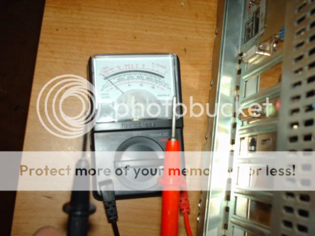
** Before we continue, please make sure that you NEVER touch the two test probes on your multimeter together while the unit is switched on. This could damage the multimeter. Also, never allow the test probes to touch the incorrect wires (IE: negative probe onto a positive lead, or the positive probe onto a negative lead) as that could damage the unit and/or whatever you are testing. **
There is two ways to do this. Method one is easier than method two, but it requires a power supply with a 20+4 pin connector. Method two works just as well, but takes a tad longer.
METHOD ONE:
With your PC off, switch the power supply off and unplug all devices connected to it (except the motherboard). Take your multimeter and set it to 15DCV. Now, grab a molex plug and stick the black (negative) test probe into either of the two black pins on the molex. Make sure it stays in place, you don't want it to fall out. Also make sure that it doesn't contact any metal or anything conductive.

Disconnect the 4pin connector from the 20pin ATX connector block. You will have one orange, one yellow, one black, and one red wire coming out of this plug.

Switch on your power supply. and turn on your PC. Make sure you don't allow the red (positive) test probe to touch any metal or wires.
Take your red (positive) test probe and decide which rail you'd like to test. As mentioned above, you can test the +12V, the +5V, and the +3.3V rails with this plug.
To test, simply touch the end of the red (positive) test probe to the corresponding wire. IE: To test the +12V rail, touch the test probe to the tip of the YELLOW pin.

METHOD TWO:
If you don't have a 20+4 pin ATX connector, or don't feel like taking the 4pin connector off, use this method.
For method two, we have to use the molex and 20pin ATX connector.
Insert the black (negative) test probe into either black pin. Insert the red (positive) test probe into the yellow pin. This will give you your +12V rail measurement.

Insert the black (negative) test probe into either black pin, and insert the red (positive) test probe into the red pin. This gives you the +5V reading.

For the +3.3V reading, it gets a little tricky. Stick the black (negative) test probe into either black pin on the molex connector. Then, take your red (positive) test probe and cram it into the fitting on the back of the orange pin on the 20pin ATX connector. You should have enough room to get the test probe in there. Make sure you use the ORANGE wire (there are several orange ones, any will do).

Remember that having unplugged all devices, this is your voltages are idle. Jot this down, and then plug all your devices back in and test it again. Write this down, and then run prime95 (In-place large FFT's) and then test voltages again. You could even run 3DmarkXX or play an intense video game and again check the voltages.
The point I'm trying to get across is that as the system strains, it draws more power. IE: A video card consumes a lot more power more in 3D mode than in 2D mode, etc.
Nitestick mentioned there being different +12V rails, so I'm going to
add to the guide how to check those as well.
In your typical dual +12V rail power supply, the first rail will be the 20(+4)
pin ATX connector, and the 4/8pin CPU power connector. Rail 2 will be everything
else.
To measure the ATX connector you'd have to stuff your test probes into the back
of the connector. With my powersupply and multimeter, that wasn't quite possible
(it didn't fit). So, what I did was took a pin and wedged it into the back of
the connector. If you do it right, you should get it wedged in pretty far. Now,
this is dangerous because if it happens to fall out and lands on your PCB,
you're going to have problems, so make sure you stuff it in there real far. Put
them in with your system OFF and power supply OFF or unplugged, and when they're
stiff and ready you can turn it back on.
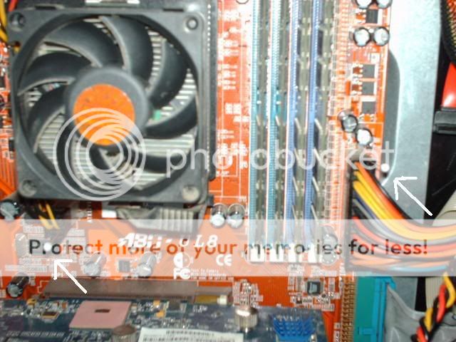
How I did mine was I stuck one pin in the 4 pin CPU power connector, and one in
the actual ATX connector. I did this so I didn't accidently connect the two and
short it out.
You can see the pins marked by white arrows.
Now, some of the newer power supplies can have three or more +12V rails. I'm not
entirely sure what will be hooked up to what rail, but I'm guessing it would go:
+12V1 = ATX and CPU power, +12V2 = molex and floppy, +12V3 = PCI-e and
SATA....etc. If you look in the user manual that came with your power supply, it
should tell you which rails do what...just remember that yellow = +12V, and
black = ground.
Here is how you measure the PCI-e connector. Now, just for the picture I have my
test probes through the back of the connector. This is because you can't insert
it into the front like you can with a molex, so just so they wouldn't move for
the picture, I did it this way (I don't have three hands, lol). Though if you
can't get it through the back, you can prop the connector up and touch the test
probes to the end of the pins on the front.

I was bored, and needed to check my old system due to some problems....so I figured I'd make a guide while I was at it.")
Hope someone learns something.
Updated 10/01/07
Ok, first you need a multimeter that can handle 15 DC volts. You can get a cheap one (like mine) at Radio Shack for about 15$.
Next, we need to understand which wires do what on the power supply. You will be dealing with only four different wires, here they are:
YELLOW - This is your +12V rail
RED - This is your +5V rail
ORANGE - This is your +3.3V rail
BLACK - This is a ground
** Before we continue, please make sure that you NEVER touch the two test probes on your multimeter together while the unit is switched on. This could damage the multimeter. Also, never allow the test probes to touch the incorrect wires (IE: negative probe onto a positive lead, or the positive probe onto a negative lead) as that could damage the unit and/or whatever you are testing. **
There is two ways to do this. Method one is easier than method two, but it requires a power supply with a 20+4 pin connector. Method two works just as well, but takes a tad longer.
METHOD ONE:
With your PC off, switch the power supply off and unplug all devices connected to it (except the motherboard). Take your multimeter and set it to 15DCV. Now, grab a molex plug and stick the black (negative) test probe into either of the two black pins on the molex. Make sure it stays in place, you don't want it to fall out. Also make sure that it doesn't contact any metal or anything conductive.
Disconnect the 4pin connector from the 20pin ATX connector block. You will have one orange, one yellow, one black, and one red wire coming out of this plug.
Switch on your power supply. and turn on your PC. Make sure you don't allow the red (positive) test probe to touch any metal or wires.
Take your red (positive) test probe and decide which rail you'd like to test. As mentioned above, you can test the +12V, the +5V, and the +3.3V rails with this plug.
To test, simply touch the end of the red (positive) test probe to the corresponding wire. IE: To test the +12V rail, touch the test probe to the tip of the YELLOW pin.
METHOD TWO:
If you don't have a 20+4 pin ATX connector, or don't feel like taking the 4pin connector off, use this method.
For method two, we have to use the molex and 20pin ATX connector.
Insert the black (negative) test probe into either black pin. Insert the red (positive) test probe into the yellow pin. This will give you your +12V rail measurement.
Insert the black (negative) test probe into either black pin, and insert the red (positive) test probe into the red pin. This gives you the +5V reading.
For the +3.3V reading, it gets a little tricky. Stick the black (negative) test probe into either black pin on the molex connector. Then, take your red (positive) test probe and cram it into the fitting on the back of the orange pin on the 20pin ATX connector. You should have enough room to get the test probe in there. Make sure you use the ORANGE wire (there are several orange ones, any will do).
Remember that having unplugged all devices, this is your voltages are idle. Jot this down, and then plug all your devices back in and test it again. Write this down, and then run prime95 (In-place large FFT's) and then test voltages again. You could even run 3DmarkXX or play an intense video game and again check the voltages.
The point I'm trying to get across is that as the system strains, it draws more power. IE: A video card consumes a lot more power more in 3D mode than in 2D mode, etc.
Nitestick mentioned there being different +12V rails, so I'm going to
add to the guide how to check those as well.
In your typical dual +12V rail power supply, the first rail will be the 20(+4)
pin ATX connector, and the 4/8pin CPU power connector. Rail 2 will be everything
else.
To measure the ATX connector you'd have to stuff your test probes into the back
of the connector. With my powersupply and multimeter, that wasn't quite possible
(it didn't fit). So, what I did was took a pin and wedged it into the back of
the connector. If you do it right, you should get it wedged in pretty far. Now,
this is dangerous because if it happens to fall out and lands on your PCB,
you're going to have problems, so make sure you stuff it in there real far. Put
them in with your system OFF and power supply OFF or unplugged, and when they're
stiff and ready you can turn it back on.
How I did mine was I stuck one pin in the 4 pin CPU power connector, and one in
the actual ATX connector. I did this so I didn't accidently connect the two and
short it out.
You can see the pins marked by white arrows.
Now, some of the newer power supplies can have three or more +12V rails. I'm not
entirely sure what will be hooked up to what rail, but I'm guessing it would go:
+12V1 = ATX and CPU power, +12V2 = molex and floppy, +12V3 = PCI-e and
SATA....etc. If you look in the user manual that came with your power supply, it
should tell you which rails do what...just remember that yellow = +12V, and
black = ground.
Here is how you measure the PCI-e connector. Now, just for the picture I have my
test probes through the back of the connector. This is because you can't insert
it into the front like you can with a molex, so just so they wouldn't move for
the picture, I did it this way (I don't have three hands, lol). Though if you
can't get it through the back, you can prop the connector up and touch the test
probes to the end of the pins on the front.
I was bored, and needed to check my old system due to some problems....so I figured I'd make a guide while I was at it.
Hope someone learns something.
Updated 10/01/07